Zemax Optical Simulation
We use Ansys Zemax OpticStudio to simulate the optical system of the OGS, validate component selection, and determine requirements and parameters for the operation of the OGS. We have performed the following investigations using Zemax.
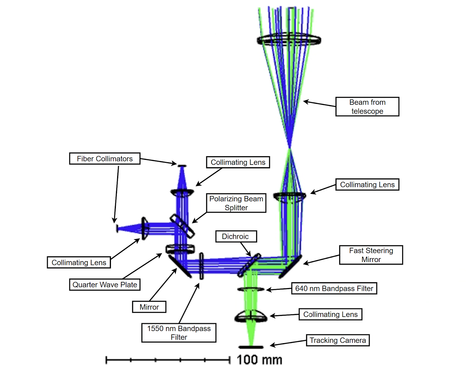
Incidence Angle for FSM
Zemax is currently used to analyze the FSM’s sensitivity to incidence angle in order to determine the acceptable range of beam deviation that will still allow light to couple onto the detectors.
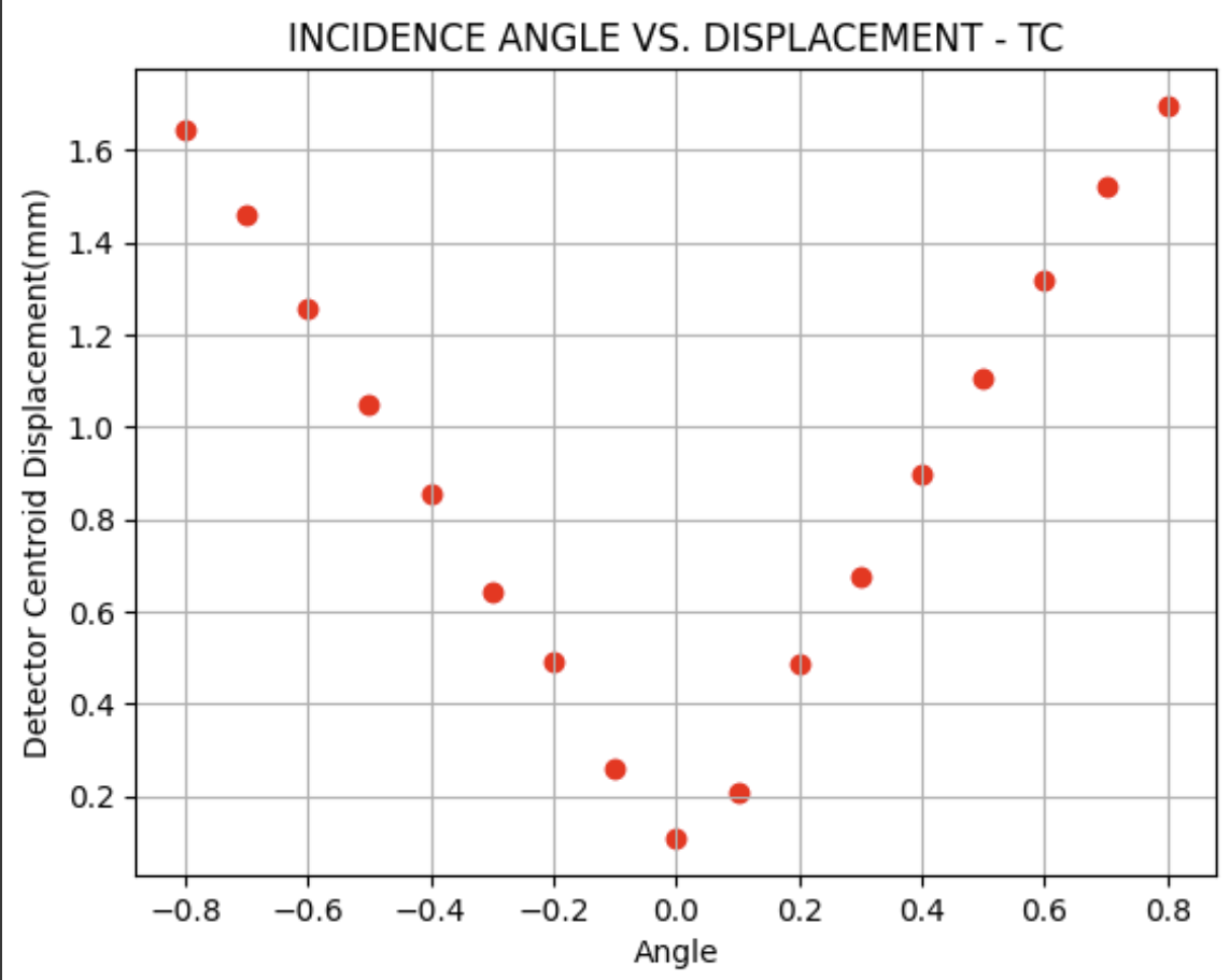
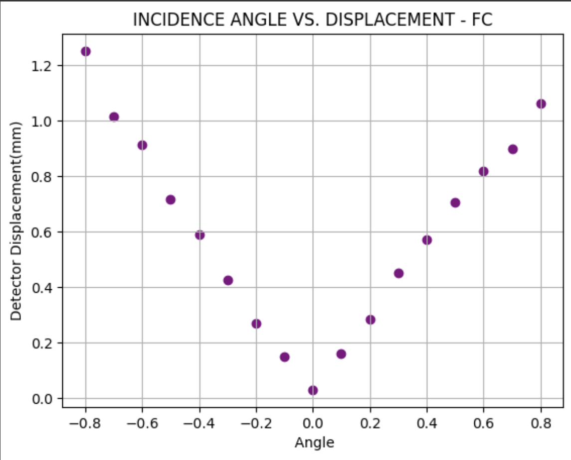
In this simulation, the incoming light source is tilted from the ideal perpendicular angle to imitate a potential deviation. To produce the most accurate results, the maximum angle shift was constrained to prevent significant errors in system performance, such as incorrect polarization or wavelength reaching the detectors due to misalignment. For each angle within this range, irradiance data at the tracking camera and fiber collimators were used to determine the beam centroid’s displacement from the center of the detector. The centroid and the incidence angle have a linear correlation and a tolerancing margin of ±0.8°.
Below: Relationship between FSM incidence angle and detector displacement for the fiber collimators (right) and tracking camera (left).
|
|
FSM Shift
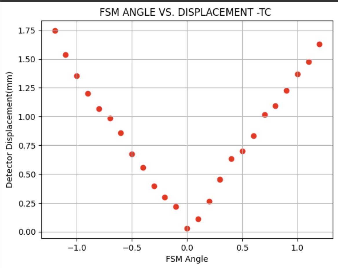
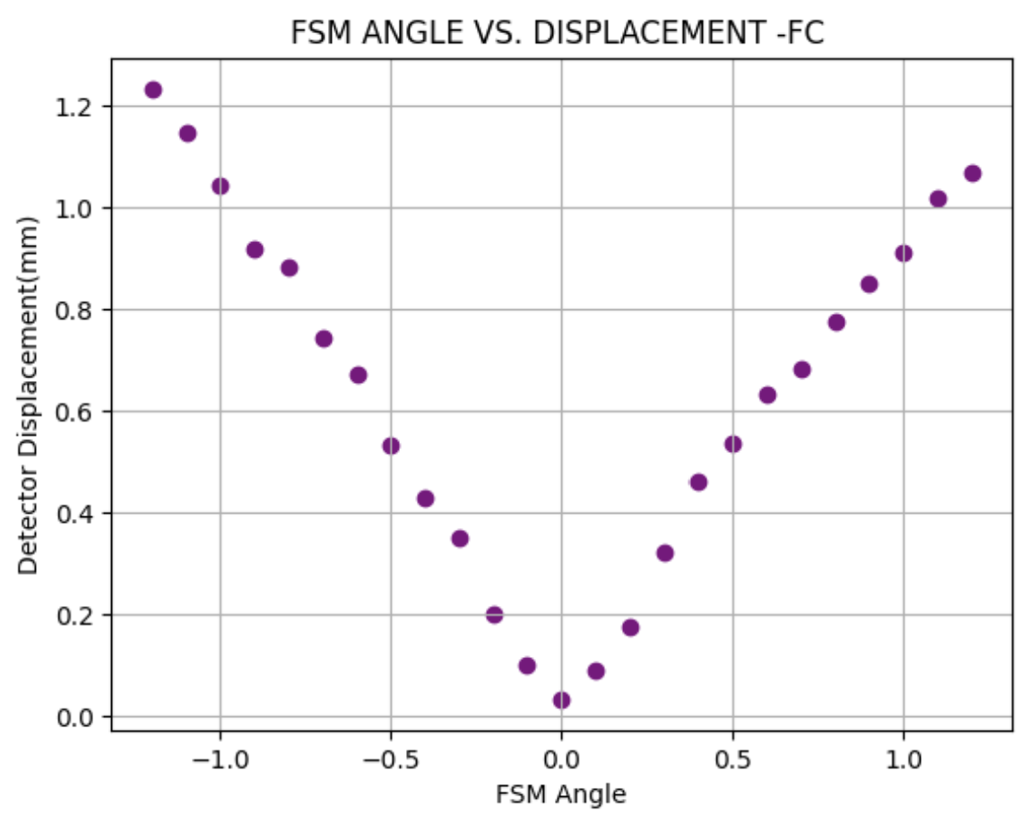
The limits of the FSM’s physical shift were also tested to ensure flexibility in the mirror’s movement to accommodate any positional deviations of the beam. To simulate these effects, the FSM’s tilt was slightly adjusted until the beam was no longer centered on the following components and began producing damaging back reflections. Similar to the incidence angle test, irradiance centroid data for the tracking camera and fiber collimators were analyzed. The centroid position and FSM tilt show a linear relationship with a functional range of ±1.2°. This indicates that the FSM can compensate for slight hardware misalignments or beam shifts while maintaining proper system performance.
Below: Relationship between FSM tilt and detector displacement for the tracking camera (left) and fiber collimators (right).
|
|
FSM Diameter
The FSM chosen for our optical path is 1 inch in diameter because it is compact enough to fit within the constraints of the setup, but possessing an aperture large enough to allow for tolerancing. If we were to employ a 15 mm FSM to save space, we would observe an increased amount of stray light and back reflections as the FSM would be too small to reflect the entire beam’s diameter. A 31 mm FSM would cause more constraint within the system and would allow for a larger range of angles due to its increased size; however, the centroid deviation for the tracking camera is greater within the same ±1.2° and ±0.8° angle ranges. This signifies that the 31 mm FSM has a larger tolerancing margin for both incidence and FSM angle shifts, but there is more power loss at the detectors due to the light being significantly off-center. These comparisons show that the 25.4 mm FSM is ideal for the OGS setup because it optimizes power at the fiber collimators and tracking camera while still maintaining a reasonable range of error.
Numerical Aperture
Our ray tracing analysis conducted with various FSM parameters confirms that the numerical apertures of the fiber collimators are not a limitation for this system. The numerical aperture defines the range of incident angles at which light can be coupled efficiently into the fiber, making it an important factor for beam alignment. The precise collimation provided by the focal lenses ensures that, under proper beam propagation, the light will not enter at an angle approaching the aperture limit. This is significant because it indicates that the system can run with low sensitivity and minimal power loss at the collimators. As a result, the OGS design tolerates a significant margin of error for any skew in the optical setup.
Modeling Polarization
Sequential Mode is used to simulate the change between circular to linear polarization when the data transmission beam propagates through the QWP. To create this effect, a Jones matrix with the appropriate phase shift is added to the surface of the QWP. The incoming beam must be initialized to the parameters that reflect circular polarization and then a ray trace will return the resulting graphs.

|

|