System Architecture Overview
This document serves to describe the major systems and subsystems of the satellite and how they interface, as well as explaining the reasoning behind our design choices. Our design focuses on clear subsystem roles and well-defined interfaces, ensuring that each subsystem integrates smoothly with the rest of the satellite.
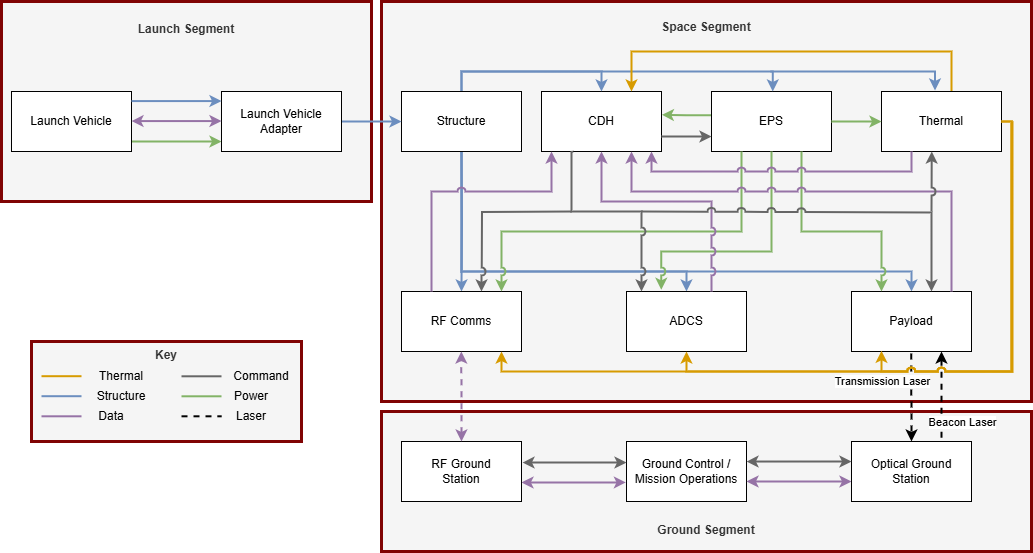
The architecture is divided into three main segments: the Launch Segment, Space Segment, and Ground Segment. The launch segment consists of the launch vehicle and launch vehicle adapter, which transports the spacecraft into orbit. The ground segment contains the ground control center, RF ground station, and optical ground station, which handle all command, control, and data reception.
I. Launch Segment
The launch segment consists of the launch vehicle and the launch vehicle adapter. The launch vehicle provides structural support, power, and data interfaces to the spacecraft during ground operations and ascent. The launch vehicle adapter mechanically connects the spacecraft to the vehicle and transfers these interfaces to the spacecraft’s structure.
II. Space Segment
The space segment contains all spacecraft subsystems required for autonomous operation in orbit. The structure provides the mechanical framework for mounting all components and relays the separation signal to the Command and Data Handling (CDH) system. CDH acts as the central processor, sending commands to and receiving telemetry from active subsystems. The Electrical Power System (EPS) generates, stores, and regulates power for all systems, while the thermal control subsystem maintains operational temperature ranges for critical hardware. RF Communications enables radio-frequency uplink and downlink with the RF Ground Station. The Attitude Determination and Control System (ADCS) maintains spacecraft orientation for communications, solar panel pointing, and optical payload alignment. The optical payload transmits mission data to the Optical Ground Station via a transmission laser and receives a beacon laser for pointing and tracking.
III. Ground Segment
The ground segment includes the RF Ground Station, Optical Ground Station, and Ground Control. The RF Ground Station handles two-way RF communication for commands, telemetry, and mission data. The Optical Ground Station receives high-speed optical downlinks from the payload and transmits a beacon laser to assist with alignment. Ground Control coordinates all mission activities, sending commands through both stations and processing incoming data for mission execution and analysis.
By structuring the satellite into clearly defined segments and subsystems with well-defined interfaces, the design ensures that each component can operate reliably while integrating into a unified system. The flow of interfaces between systems have been deliberately organized to minimize complexity, reduce integration risk, and support efficient operations. This approach provides a solid foundation for meeting mission objectives, maintaining operational flexibility, and ensuring the spacecraft can perform effectively throughout its lifecycle.