Laser Driving
Overview of Requirement
The laser driving setup generates two orthogonal, high-purity linear polarization states. In the Injection Assembly, each state passes through a quarter-wave plate, converting it to either right-handed (RCP) or left-handed (LCP) circular polarization. Using FPGA-controlled modulation at 1–10 MHz, this implements Circular Polarization Shift Keying (CPolSK), where binary data is encoded in the handedness of the light—left for one bit value, right for the other.
Further details on the payload assemblies are provided here.
Other literature describes alternative approaches, such as employing a single laser with a fast electro-optic modulator to switch polarization states. However, the resulting modulation scheme is functionally the same. Despite using different hardware paths, they ultimately transmit the same sequence of right- and left-handed circular polarization states to encode the data.
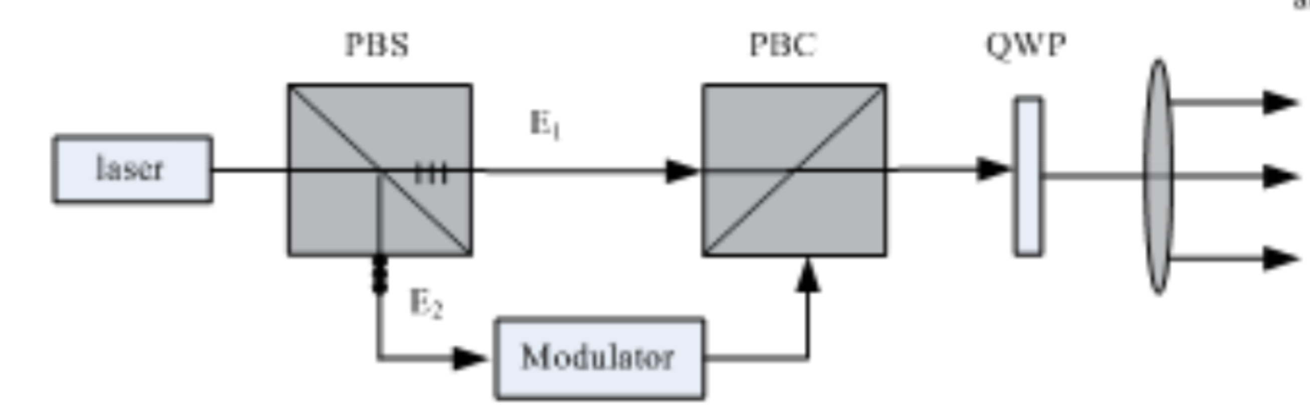
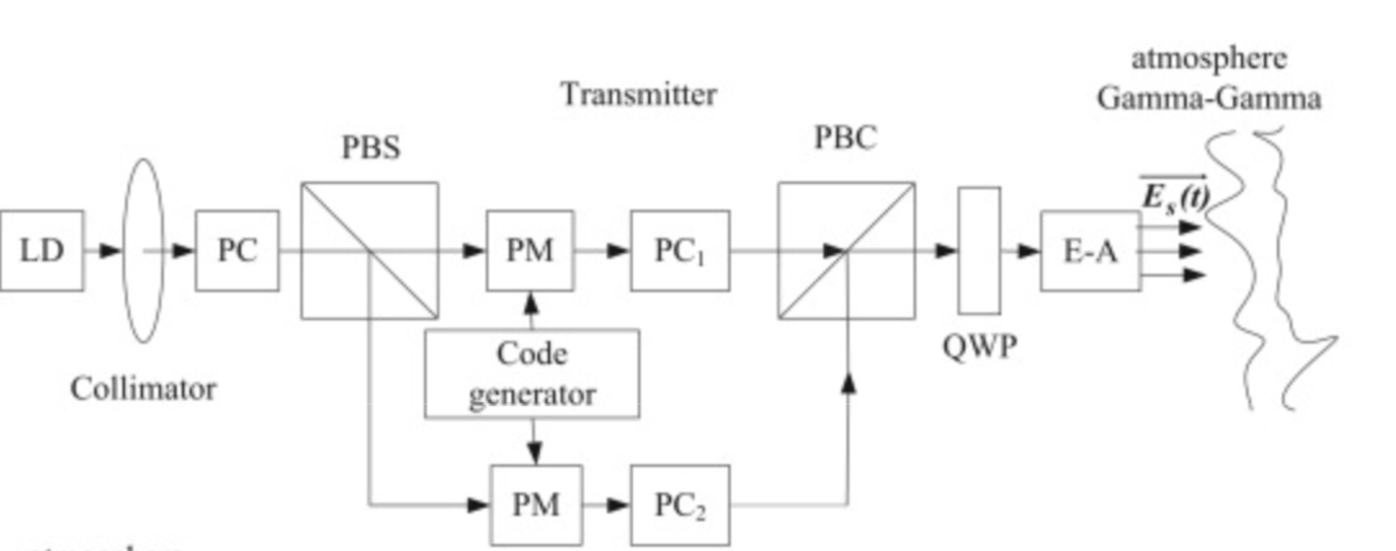
Typically, circular polarization shift keying is achieved by: . Using a polarization beam splitter to split the light into its constituent orthogonal polarizations, X and Y. . Passing one of the orthogonal components through an electro-optic modulator (EOM), which introduces a ±𝜋/2 phase shift between the X and Y components. . Recombining the two components to give RCP and LCP [6, 7, 11].
Examples are shown below:
Background
Free space optical (FSO) communications have often relied on phase and intensity modulation schemes to transmit data; on-off keying (OOK) is a low-complexity, cost effective modulation scheme that has been used in many such communications systems [1, 2]. However, due to atmospheric interference, phase noise and scintillation effects are introduced into the modulated beam, leading to poor data quality, and high bit error ratio (BER) [3]. On the other hand, the state of polarization (SOP) of light is relatively well preserved over long distances, making it an ideal data carrier for deep space FSO communication systems [4, 5, 12].
Circular Polarization Shift Keying, or CPolsk for short, refers to a polarization modulation method in which 1s and 0s are encoded in either left or right handed circular polarizations of light. The circular nature of the polarization allows for information to be decrypted without taking into account the orientation of the emitter; for instance, if one was going to encode information in horizontal or vertical polarization, you would have to keep track of the rotation of the emitting satellite relative to the observer, something that would be much more complicated in the case of orbiting bodies [6, 12]. Circular polarization states, on the other hand, transmit maximum intensity regardless of relative orientation of emitter and source.
We had originally intended to use a polarization switch that changes the relative phase between two orthogonal linear polarization components. The device supports an input containing both polarization components and applies a phase shift to one of them. Each orthogonal component of the light would then pass through a quarter-wave plate (QWP), with one component oriented at −45° and the other at 45°, producing right- and left-circular polarization (RCP and LCP). Unfortunately, by CubeSat standards, our payload box is slightly larger than 1U, making most commercially available, space qualified polarization switches too large to fit in our design. A significant portion of our design planning and research was devoted to finding such components that would fit our requirements. While there were a few manufacturers with suitable products [8, 9] that were willing to modify their designs to fit within our systems, we would have had to pay additional fees to have them undergo space qualification (which includes costs for design modifications and testing). Furthermore, the timeline for testing such a product would have interfered with our own project timeline.
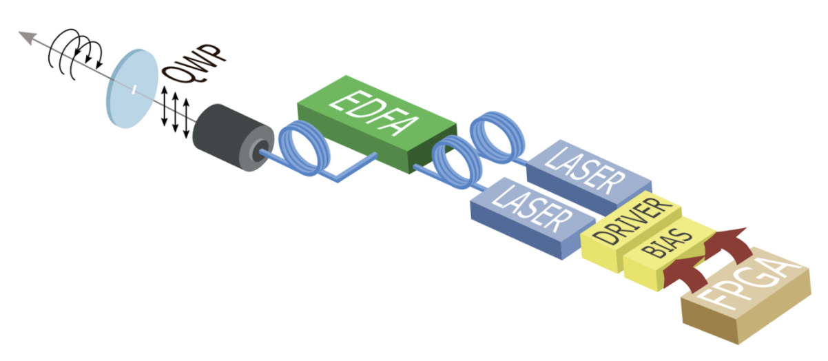
To test our design capabilities of ON/OFF modulations at 10MHz, we are working with a driver (Thorlabs LD1101) and bias (Thorlabs T-Bias) from Thorlabs. We use a Field-Programmable Gate Array (FPGA) as a signal generator, which routes a signal into the bias for one of the two lasers. Crucially, when one of the lasers is on, the other one is off, such that at a given point of time, only one of the two orthogonal linear polarizations is being transmitted through the Payload setup. We use a Thorlabs 2x1 fiber combiner to create a single optical path output. Next, the signal is amplified from approximately 5mW to close to 230mW using an Erbium-Doped Fiber Amplifier (EDFA). The amplified linearly polarized signal is passed through a quarter wave plate (QWP) oriented relative to the incident beam such that there is a ±45˚ angle between the fast axis of the QWP and the SOP of the beam, with a +45˚ angle yielding RCP and -45˚ yielding LCP [10]. This setup essentially leverages the cost-effective, low-complexity system requirements of OOK to emulate CPolSK for high quality data transmission.
Components
1550nm Lasers (Linearly Polarized)
The 1550nm lasers output a maximum of 5mW. The signal is later amplified using the EDFA which requires a minimum of >5mW on the input.
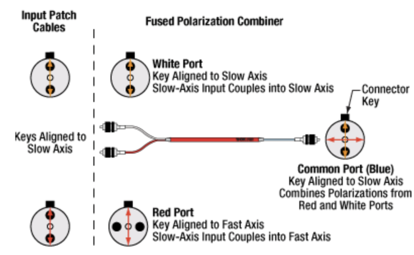
2×1 Fiber Combiner
The 2x1 Fiber Combiner from Thorlabs has two inputs and one output. The input patch cables from the laser have their keys aligned to the slow axis. At the combiner, the white port supports a slow-axis to slow-axis coupling, whereas the red port supports a slow-axis to fast-axis coupling. This creates two paths where the beams are linearly polarized and orthogonal. This is important because it will serve as a basis for switching between RCP and LCP.
Polarization-Maintaining (PM) Fiber
The linearly polarized lasers are PM coupled so that SOP can be preserved. We expect there to be misalignments. You can read more about it on the characterization of our PM fibers here.
FPGA (Field Programmable Gate Array)
Provides the encoding in binary data which allows us to communicate data via CPolsk, effectively functioning as our signal generator. It does it by sending the ON/OFF commands at the correct modulation speeds through the T-Bias. More on the FPGA selection and options we have considered here. .
Driver Thorlabs LD1101
Laser-diodes require particular current control to operate safely and properly. This is because once the laser receives a current that exceeds the threshold current, the power increases significantly. If the current is not properly introduced, it could even exceed the maximum rated drive current, which can cause irreversible damage through overheating or catastrophic optical damage (COD) at the laser facet. Thus, to control the laser’s output power, a driver circuit is used to regulate the current flowing into the laser diode. This circuit typically uses the output from a built-in photodiode to monitor the emitted light in a feedback loop form and adjust the drive current. This will ensure stable operation.
T-Bias Thorlabs T1G
Many laser drivers are designed for precision only, not speed, and have bandwidths in the kHz range. For ON/OFF modulation in the MHz range, there needs to be a way to bypass the driver’s limited bandwidth and inject the high-frequency signal directly into the laser diode while still maintaining the correct DC bias. Thus, a bias tee is used to maintain a steady DC current going into the laser and a high-speed modulation from an RF source. The RF input is a high-frequency electrical signal from a source like a function generator. In our case, we have an FPGA.
Options Considered
| Option | Description | Pros | Cons | Estimated Relative Cost |
|---|---|---|---|---|
01 |
1 Polarization Switch EOM, 1 laser, 1 QWP, and no PBC/PBS |
Highly compact setup |
Highly cost prohibitive compared to other set up options. It requires extensive testing due to specificity of requirements, size constraints |
High |
02 |
1 linearly polarized laser, PBS splits into X/Y components, one component is shifted by 90˚, components recombined using PBC. Typical setup in literature |
Relatively simple, verified by literature [6, 7, 11] to work for CPolSK. The type of EOM used in this setup is more commonly used and therefore less expensive. No QWPs required, circular polarization comes from superposition of two linearly polarized lasers. |
Still requires a compact space hardened high speed modulator. Incredibly path length sensitive — small differences or changes in path length between the two laser paths en route to exit could dramatically change relative phase and cause the output to become more elliptical. Possibly increased ellipticity due to attenuation of modulated component in the EOM, but no change in the amplitude of the unmodulated component. More components to fit in due to PBS and PBC. High difficulty. |
Medium |
04 |
2 Lasers, 2 Drivers, 2 T-Bias, ON/OFF modulated by 1 FPGA |
Cost efficient, simpler setup, no EOM required, no PBC/PBS required. |
At high modulation speeds, this set up is relatively difficult to get 0W output from either laser in the ‘off’ setting, which might introduce error/ellipticity into the output beam. May also introduce leakage on the ON state. |
Low |
Resources
Next Steps
Current state: successful modulation of 1 laser has been achieved. Our next steps are: * Ensure that ON/OFF modulation speeds lead to corresponding optical power changes of same or close speeds. * Duplicate the system so that there are two modulated lasers. * Synchronize the ON/OFF commands for the two lasers. * Record frequency of optical powers.
Challenges to Work On
We expect that turning the laser ON and OFF at 10 MHz means each modulation cycle lasts only 100 ns. If the laser’s driver or the diode itself cannot switch fully within this short period due to finite rise and fall times, the output may not reach the full ON level before switching back OFF, and may not decay completely to zero before switching back ON. This incomplete settling leads to a residual output during the intended OFF state and a reduced peak power during the ON state, effectively preventing the laser from being fully OFF.
References
-
https://www.sciencedirect.com/science/article/pii/S0030401817310428#fig3
-
https://www.exail.com/product/polarization-switches-scramblers
-
https://www.thorlabs.com/newgrouppage9.cfm?objectgroup_id=7234
-
https://www.sciencedirect.com/science/article/pii/S0030401814006981
-
https://opg.optica.org/jocn/fulltext.cfm?uri=jocn-1-4-307&id=185139